Connecting the uSDX+ Up for Digital Modes

I've been fiddling with the uSDX+ "white button" version the last couple days. As with its "brick" cousin, this one was pretty easy to connect up for digital modes. I used the BTECH APRS-K1 audio cable to get audio in/out of the radio; it plugs in perfectly in the back, and "just works".
Originally, I was using VOX, as I had done with the brick. However, getting the settings just right for VOX to work properly was a pain. So, I decided to make a PTT circuit. I went looking for an optocoupler, and realized that the "EasyDigi" type boards I had laying around not only had the optocoupler, they also had a nicely soldered completed PTT package ready to go. So, I got an unsoldered kit and put it together most of the way, leaving out the two transformers (I can always put them on later, if I want to use the full board.) I soldered a USB-to-TTL cable, and connected it all up.
Unfortunately for me, the RTS signal on the board was inverted, which meant that the radio was keyed up all the time, except when the software (JS8Call) wanted to transmit, when it put the radio in RX. Opposite of my need, of course. FLDigi and FLrig both have a setting to invert the RTS level (tested and worked), but JS8Call does not.
Thankfully, I've run into this problem before, and I already had a little inverter circuit soldered up and ready to go. The schematic is below. I used two 220ohm resistors), the schematic is the NPN version on the right. I had some BC548's on-hand when I made it, so that's what I used. Just a matter of connecting 5v, GND, and RTS from the USB-to-TTL cable to one side, and the RTS out connects to the EasyDigit RTS pin on the other side.
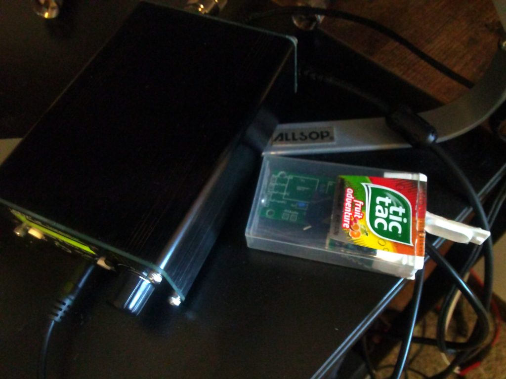
With that inverted, everything worked perfectly! The little mess fit right into a spare TicTac container that I was using to hold screws. Operated all day today with the setup shown in the photo above.
(The ATU-100 pictured was tuned to my antenna with another radio, as it needs 5W to activate and this radio only puts out 3W. Thankfully, the EFHW only needed light tuning, and the ATU-100 holds the tuning setting through power cycles; to
preserve the battery for use all day, I only turned it on when I was making longer transmissions. The EFHW was at 1.8 with the tuner off, and at 1.2 with the tuner on; both worked, but 1.2 was preferred for long TXes!)